DIAGRAM Schematic Circuit Diagram Hall Effect The hall effect sensor we will use in this circuit is an A1302 hall effect sensor manufactured by Allegro. This IC can detect magnetic fields. We will then connect this IC to an arduino, so that we the arduino can read the voltage output by the A1302 and we can display the readings to the computer screen. This voltage can be converted into position or distance measurements. For example, in automotive applications, wheel speed sensors use Hall Effect sensors to measure wheel rotation speed accurately; Switching Behavior: Switch-type Hall Effect sensors produce digital outputs that change state when a specific magnetic field threshold is reached
Here's an example of how you can connect this circuit to a breadboard: Arduino Hall Effect Sensor Test Code. To test the Hall effect sensor, you need to read the output pin, which is connected to Arduino digital pin 2. So basically all you need code-wise to read out the value is hallSensorState = digitalRead(D2);

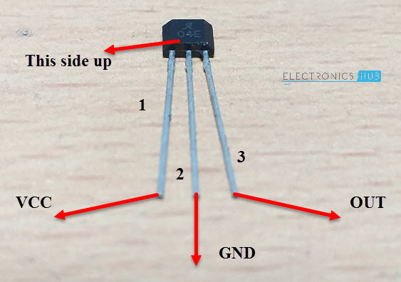
Arduino Hall Effect Sensor: How to Detect Magnetic Fields Circuit Diagram
If the hall effect sensor of diagram connect to RF (433 Mhz.) of diagram. Mathod: When magnet movement to hall sensor effect to RF (transmitter turn on) has signal to RF (receiver). And RF (receiver) of diagram display to LED lights turn on. Could you please write a circuit diagram for me. Thank you very much. Phuvadol (From Thailand)

Here we use a DRV5013 Hall Effect sensor from texas instruments, it is a digital latch Hall effect sensor. It operates with wide voltage ranges (2.5 to 38V) and provides bipolar switching. This sensor has reverse supply protection up to -22 volts and also outputs short circuit protection with current limitation features.

Hall Effect Sensor and How Magnets Make It Works Circuit Diagram
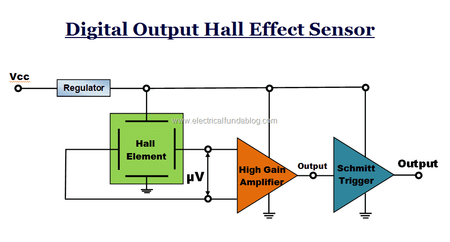
How to use Hall Effect latches and switches in practical circuits. Includes diagrams and circuits. Fig. 1. Introduction Hall Effect Switches Sensors Circuits Tutorial. by Lewis Loflin. A Hall sensor in its most basic form is an analog integrated circuit. It consists of a Hall plate that outputs a "transverse" voltage based on the intensity of a