Shock Sensor Alarm Circuit Circuit Diagram Learn how to make a very simple wireless shock, vibration, or pressure sensing alarm that can be used for a wide range of applications, including letting you Description. Here is a simple shock sensitive alarm circuit that has many many applications fro home to automobiles.The main application of this circuit is to use it as an anti theft alarm in automobiles.A peizo electric sensor is used as the shock sensor which has to mounted on the door which you have to protect.. Here the IC1 LM 3558 is wired as an inverting Schmitt Trigger.The POT R1 sets

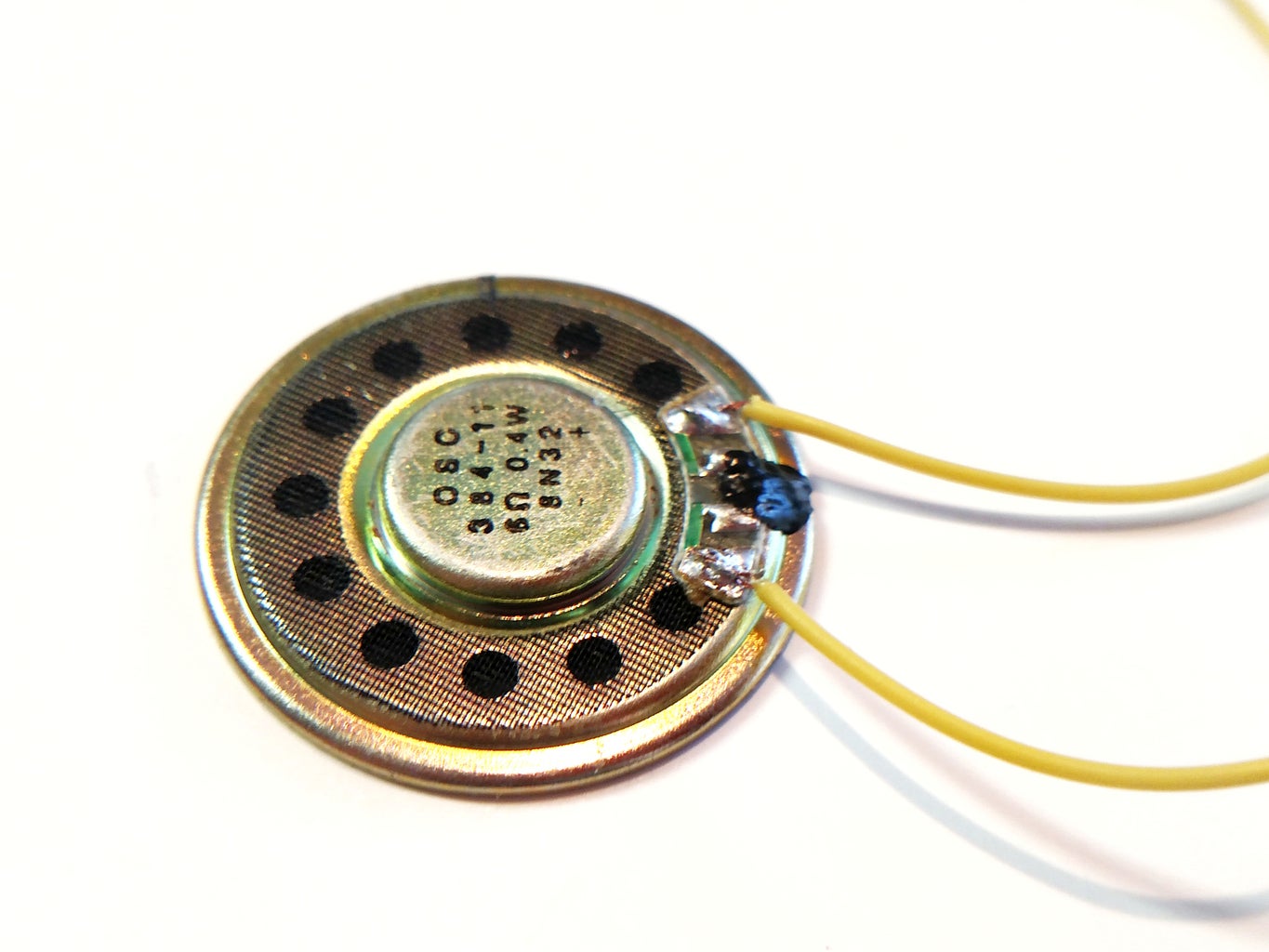
The Shock Sensor Module, also known as a vibration sensor or shake sensor, is designed to detect sudden movements or shocks. It is commonly used in security systems, impact detection projects, and interactive installations. In this step-by-step guide, we'll show you how to set up the Shock Sensor Module with an Arduino and create projects Excellent pressure sensing alarm circuit that uses a piezo wafer which has many uses!Schematic here:http://electroschematics.com/6122/pressure-sensor-alarm/C

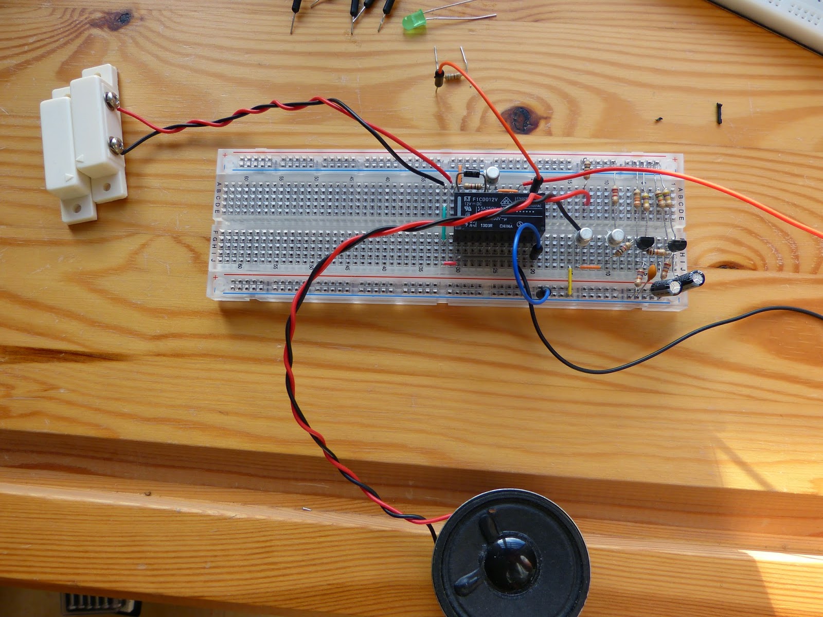
DIY Wireless Shock Vibration Pressure Alarm! (FULL SCHEMATIC) Circuit Diagram
Pendulum Style Shock Alarm. This alarm system is very useful and can be used in many different ways. It works as a sensor to detect movement and can help protect cars, big objects, houses, or other places where safety is important. By building the circuit, you can create an easy and effective way to guard against problems like theft or damage.
In this article I have explained a very simple and cheap car shock sensor alarm circuit which costs hardly 1/2 a dollar yet performs the actions reasonably accurately. The working Principle of the Shock alarm. The principle employed here is pretty basic, a mic is used to sense the impact, the sensed output is amplified by a transistorized

Shock Vibration Detector Circuit using 801S Sensor Circuit Diagram
The circuit can be powered by a voltage that can exceed 12V, which is the case in a car and almost all domestic alarm systems. Construction. The printed circuit board layout and the component placement diagram of this 801S shock sensor is shown in the Figure below. To build a Simple Shock Sensor Alarm Circuit follow the below mentioned steps: Gather all the component as mentioned in the above circuit diagram; Connect pin 1 of IC1 LM358 to anode of diode D1 and cathode of D1 to on end of buzzer and the other end of buzzer to GND.